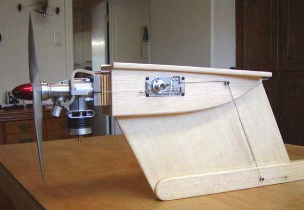
Note how two pegs are used to route the line from the pod mounted timer to be in line with the fuselage
A CLEVER WAY TO DT A HIGH THRUST LINE MODEL
Tandy Walker of Arlington, TX is known as a Master Model Builder. One of his latest projects is a Class A 500 SI T-Bird with an OS .19. Tandy has graciously shared some photos of how he does his DT system. Almost everyone will get an idea they can use out of this. Questions should be directed to Tandy.

Note how two pegs are used to route the line from the pod mounted timer to be in
line with the fuselage
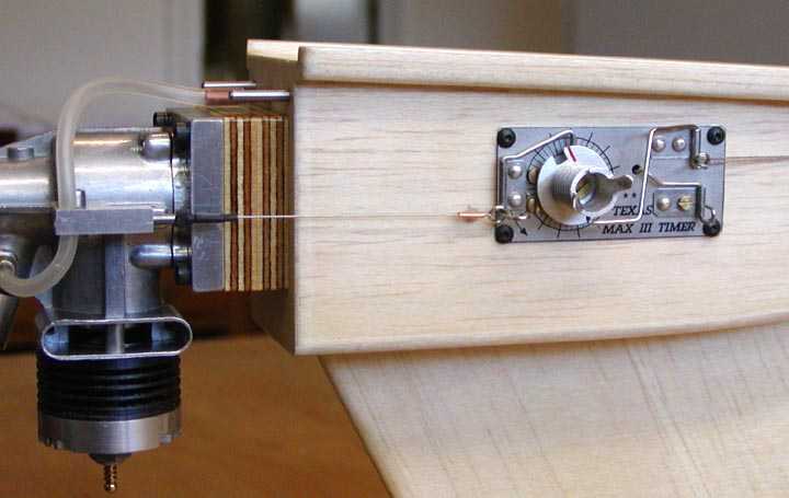
Tandy has used a hard tank in the pod that is pressurized by the engine
crankcase.
The plane came out tail heavy and he needed to shim out the motor to get the
proper CG.
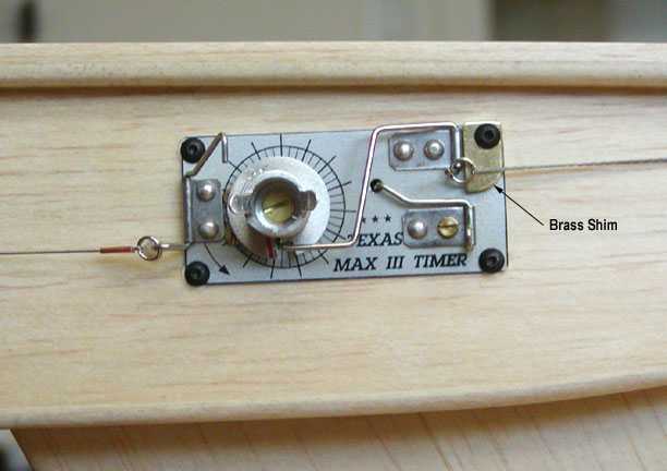
This is a later change to add the shim at the DT post to prevent the split ring
from sliding too low. An important thing to do.
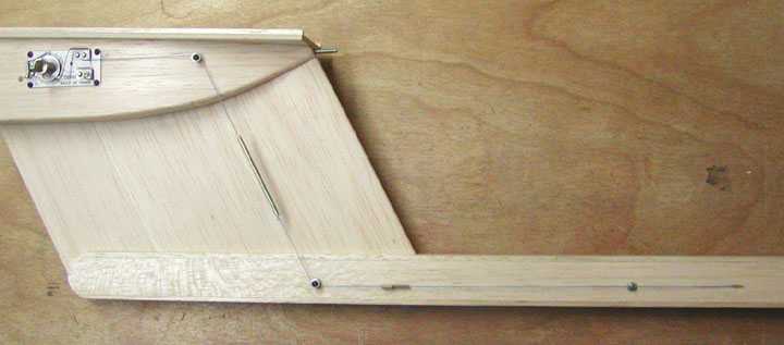
The DT line is routed inside the fuselage back to the rear end. The line limit
stop is to the left of where the
line enters the fuselage.
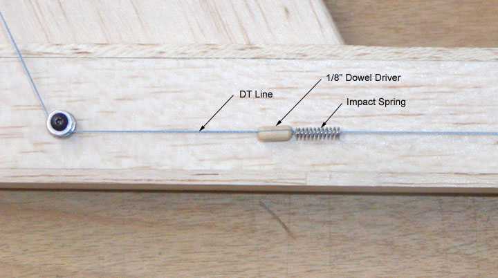
This is a close up how he limits the line travel to set the stab at 45 degrees
for DT. The dowel is the limit and the spring takes
up the shock of it striking the stop.
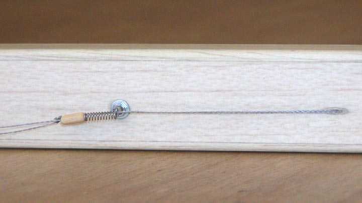
This shows how the dowel, spring, and stop work together to control how far the
stab will lift at DT.

This shows how Tandy routed the DT tube inside the fuselage at the tail. The
line going up goes to the stab.
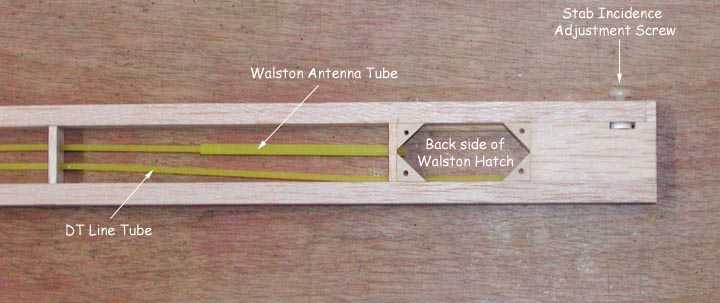
More detail of the tail end. I would definitely not suggest the Walston
transmitter be located here as it tends to make the plane tail heavy.
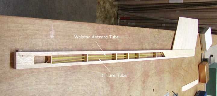
This gives you the overall of the fuselage with DT line Tube routing.
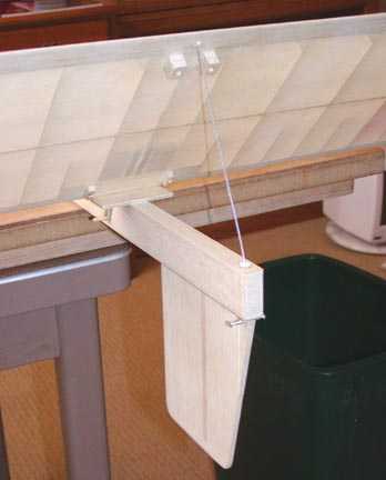 This
shows the working tail end. The DT line is routed inside the fuselage inside
some tubing. The line comes up through a hole drilled in a nylon screw that is
used for fine adjustment of stab incidence. Note the use of front and rear keys
to hold the stab in proper alignment when pulled done on the stab platform.
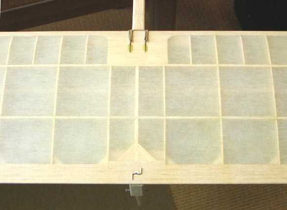 This
is the stab in the pulled down power and glide position. The double bent piece
of wire is used to retain the DT line. Notice that for transport, the wire will
slip through the trailing edge so the stab can be removed from the plane.