
HOW TO INSTALL YOUR TEXAS TIMERS BRUSHLESS MOTOR TIMER
This will walk you through what is hopefully a clear and simple procedure that will get you up flying and enjoying electric flight without pain. Although this product was developed with the E-36 event in mind, the installation shown will work with any electric plane and is also suitable for AMA Electric A or B as well as F1Q. First, lets get the general electrical hookup in mind. The below drawing is quite simple. The three wire cable from the ESC (Electronic Speed Control) is typically long, allowing you to locate the ESC close to the motor and the PLSR1 where desired. The three wire cable can then reach the connector on the PLSR1 board. This board can be located to suit your needs. I personally like to have it just an inch or so forward of the timer.
A few notes are in order here. The optional switch shown in the battery red wire line. is no longer suggested. The switch adds too much loss. To avoid a slow battery drain even when the timer is off and the motor is not running you should unplug the battery from the ESC. All ESCs will draw some power when just sitting idle. If left over night, your LiPo will be dead and perhaps ruined as they do not like to be run down to 0 volts. (Ask me how I know this is true.) The switch is also a back up safety to prevent inadvertently starting the motor. The switch and connectors used in the battery line have to be suitable for the current used by the motor. You must have the battery connecter so you can remove the battery to change it or to charge it.
The three wires from the ESC going to the motor are all the same length and same color. I am not aware of any standard in the color of these wires. The three wires in a cable from the ESC have a three pin female connector at the end where it attaches to the male ESC connector of our PLSR1. The middle wire (+) is always Red. I have seen Brown and Black for the lower wire (-) but others are possible. The top wire (S) is normally White or Orange. This is the signal wire to tell the ESC what to do with the motor. The length of this wire as supplied with the ESC is normally quite long, seven inches or so. The two wire cable from our MICRO E is Brown and Red. It uses only two of the three pins on the Timer side of the PLSR1.
This example assumes you have a removable hatch on the bottom of the fuselage for access to the various electrical components. Unless you mount battery on the outside of the fuselage, you will always need access to it. Later on I will show you a way one modeler does it that at allows access to the timer components without such a hatch. While I am thinking of it. I have had good results using the industrial strength Velcro sold at Lowe's to mount my 2S battery. So far it has held it in place, even under a real nasty ground strike. Remember, this is the heavy duty Velcro, not the stuff at Wal-Mart or a dress shop.
Now, lets look how one goes about installing the timer components.
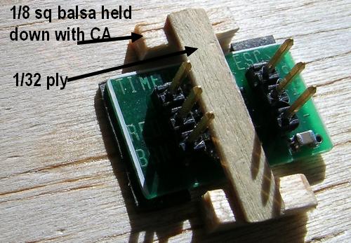
On the left is the MICRO E timer. Installation is normal and usual for this. I
suggest use of a thin ply frame on the outside to screw the faceplate down. . Don't break
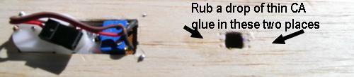
the red and brown wires on the switch. The wire colors here mean nothing. On the right is a small cutout for the push
button switch located on the back side of the PLSR1 board. This does not have to
be a neat hole as we supply a ply plate to dress up the outside around the
switch. The thin CA shown is necessary as discussed later.
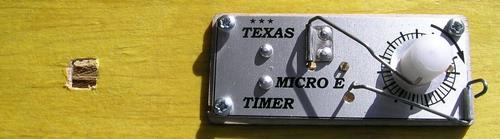
This is what it will look like on the outside of your fuselage.
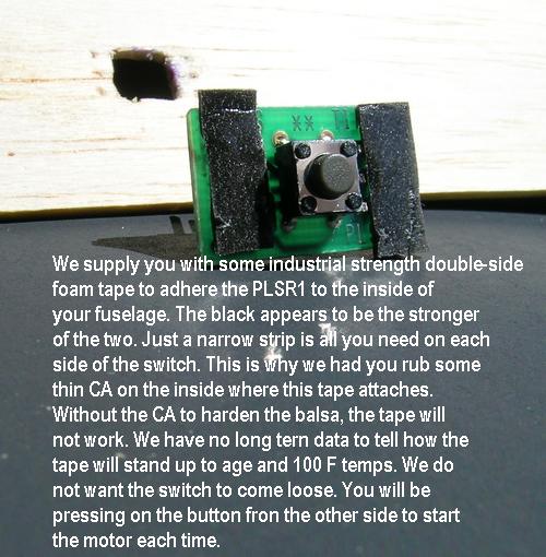
Clean off the area of the circuit board with alcohol where the tape is applied to
remove oils and any other contamination. Keep your fingers off the tape when you
remove the protective backing from each side. Press the board firmly in place on
the inside of the fuselage.
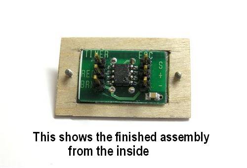
 This is what it
looks like with the board stuck in place. inside the fuselage.
This is what it
looks like with the board stuck in place. inside the fuselage.
 This
is a way to make sure the board stays in place, yet lets you remove it if
needed. It may not be needed or necessary.
This
is a way to make sure the board stays in place, yet lets you remove it if
needed. It may not be needed or necessary.
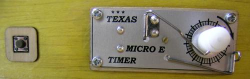
This is the finished outside with the included ply plate to make it look nice and keep
your fingers off the tissue when pressing the button to start the motor.
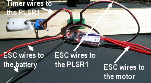
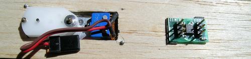
And, finally, this is what it looks like with all the wires to the various
points. As you see, there is no soldering. The two connector mate up with the
two sets of pins on our PLSR1. Most certainly, you will need to solder
appropriate connectors for the three motor wires and solder the battery up to a
connector and perhaps a switch. But, nothing from Texas Timers involves a
soldering iron in your hands. I have done it for you.
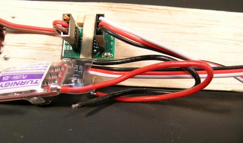
And, a close up of the two connectors in place on the PLSR1.
Should the connectors stick out too far on the inside of the fuselage, you
may carefully bend the pins over a bit. Put the connector on the pins and
support the board on the bottom so you are not bending the board and slowly push
the connector over. This is not a bend it up and down thing. One bend and leave
it.
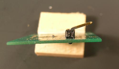
WE PROMISED YOU A LOOK AT AN ALTERNATIVE WAY TO INSTALL THE PLSR1 BOARD. HERE IT IS.
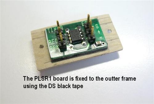
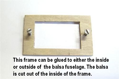
The concept here is the PLSR1 is removable from the fuselage for connecting the wires or any other service. There are two ply plates involved. The inner plate is glued to the fuselage and serves as the base for two screws holding the rest in place. The PLSR1 is fixed to the outer ply plate with the black DS tape and it has a small hole for the pushbutton switch. Here is what it looks like going together.

Obviously, you would want to make the switch hole a bit neater. This is only to
show a mounting concept. If the two screws are removed, the outer ply plate and the
PLSR1 pull out from the fuselage with the wires still attached.
QUESTIONS ABOUT SOLDERING?
As a service to our customers, I have put together some guides on how to solder small electrical items. No, for the Texas Timers product you do not know how to solder, but you will need to for the battery and motor connections. You can go Here to learn more