HINTS ON
INSTALLING THE TEXAS SOL SWITCH
The SOL switch was developed to meet the needs of the most
demanding modelers. Those who want to have perfect launch techniques and who
want to squeeze every last fraction of a second out of the engine run. It is not
something needed or even desirable for the casual flyer.
The SOL switch installation requires a fairly
precise alignment with the timer to insure correct and reliable operation. Such
installations have be done for years in F1C models. One of the ways to do this
is illustrated in the two photos below. You will note that the key to this is
putting both the timer and the SOL on the same sub-plate. The advantage of this
method are three- fold.
-
The positioning of the interference wire
can be accurately located when the timer and switch are on the same mounting.
-
The critical alignment is done with all
items in plain view.
-
The assembly can be removed for cleaning
and service and replaced with the integrity of the alignment maintained.
How the interference is done is left to the
modelers innovation. We do not believe this to be particularly critical. Almost
any force on the speed regulator (small vibrating pawl) on the timer will stop
the clock from running. No great force is needed or desirable. If the link
(wire) between the switch and timer as some flex in it, then any excessive force
should cause the wire to bow and relieve the stress. Something as simple as the
eraser of a pencil could likely work as the point of contact.
The model used for illustration in these
photo was made a a meticulous craftsman and master machinist. Such precision is
most likely not needed. The craftsman making the model did it exactly like he
would if putting the model in a plane. He used glass cloth on both sides of the
sub-plate to make it stiffer than plain plywood. Is this necessary for most
applications? Probably not.
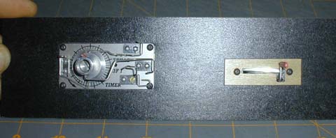
These photos of the front and back of
the assembly should give you a good starting point for your own installation.
Bill Lynch has pointed out that care must be
taken so that lines being released by the timer during flight do not catch or
snag on the SOL trigger.
We would love to have photos and details of your installations
that can be shared with others. As well as any hints problems/solutions you may have
developed or encountered.
 |
 |
| This shows the outside of the sub-plate when used with a
model 3F timer. The same techniques are applicable to any metal clock timer
using a similar clockworks. |
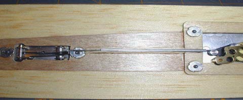
This shows the inside the fuselage side of
the sub-plate. Here, the model maker has crafted a special aluminum stop
for the end of the interference wire. Although not clearly visible, the
guide tube for the wire is glued in place. |

This is the switch installed on Gene Smith's 925 Pearl with a Texas 3F III timer

This is the sub plate I made to use on my Cox Conquest .15 powered Loose Screw A
Classic model. The timer is the brand new 3F IIIA.