USING THE MAX A TIMER IN A HIGH THRUST LINE
MODEL
Use of any dual or multi- function timer in a high thrust line
model presents a problem because the timer can not be "in line" with both the
engine and stabilizer at the same time. Mostly it is a situation of what to do
with the DT line. Larry Davidson of Moneta, VA has solved this quite neatly and
efficiently. In this case, use of the MAX IIIA timer eliminates the need for a
separate remote cutoff device for the fuel line. The same general methods could
be used in any high thrust model. See the Helpful Hints for different modeler's
solution.
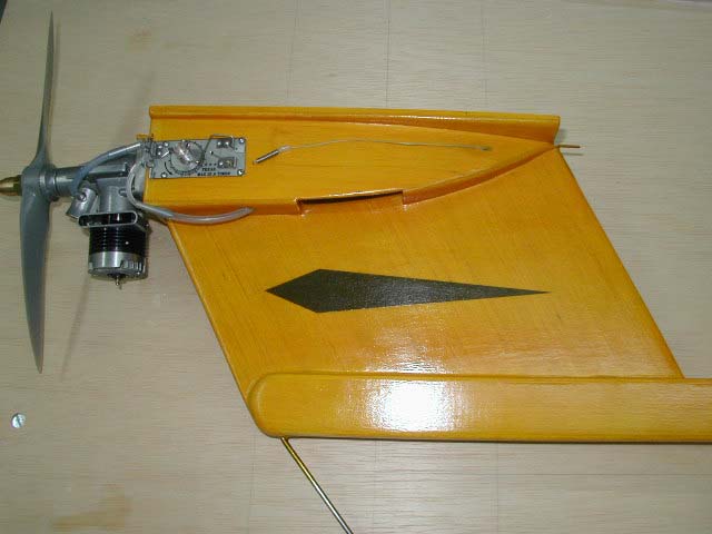
This is the completed 585 square-inch T-Bird with the MAX A timer mounted
on the engine pod. The DT line is non-stretch filament and tension is provided
by a simple spring. The spring serves as the stop where it hits the aluminum
tube going down inside the pod and pylon.
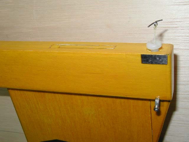
This shows how the DT line is routed down inside the pylon.
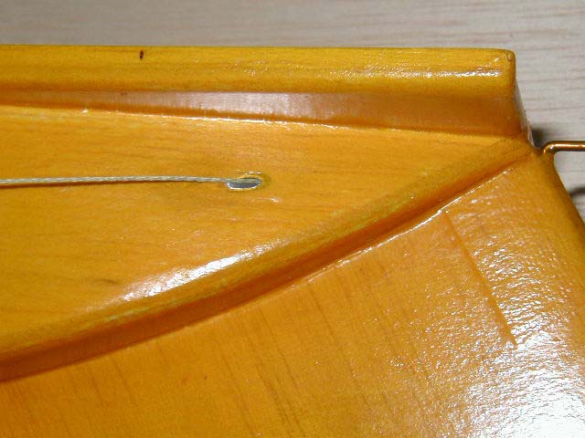
This shows the completed DT line where it will connect to the
TE of the stabilizer. Note, the nylon screw is used to set decalage.
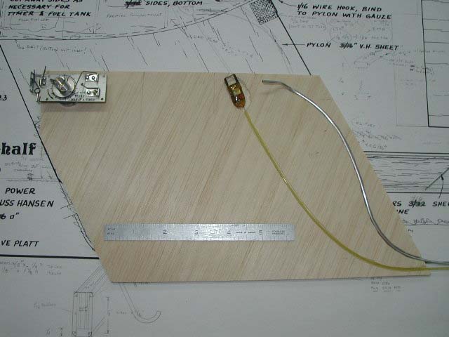
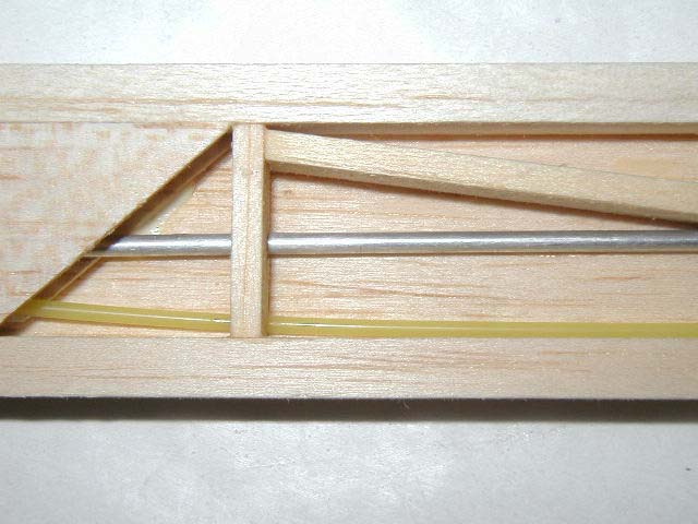
This shows the layout of the major components in the pod and pylon. The Walston
RF tracker is also shown.
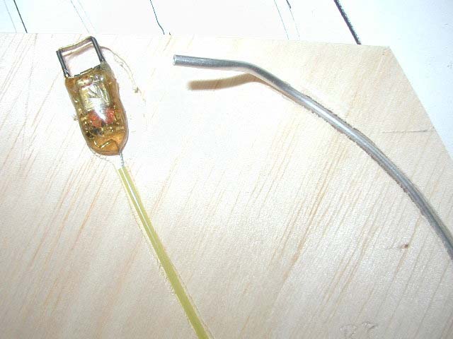
A closer look at how the Aluminum guide tubing for the DT line is shaped.
The DT line is routed inside the small aluminum tubing. The
plastic tubing is for the antenna for the radio tracker, which also installs in
the engine pod on top of the pylon.
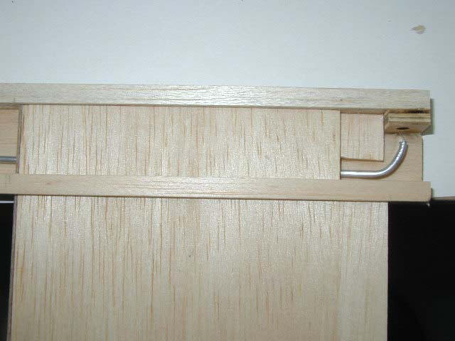
The tail end of the DT line showing how the aluminum tubing is
formed to guide the line up to the TE of the stabilizer.
Return to the MAX A Specification and Order Page

Return to the 3F A Specification and Order Page
Return to Helpful Hints